STD | API 6A | API 6B | API 17D |
---|---|---|---|
Pressure Range | up to 20.000 psi | up to 5.000 psi | up to 20.000 psi |
Ring Type Joint - RTJ | R, RX, BX | R (Oval and Octagonal) | SRX*, SBX |
Field of application | Valves, Wellheads, Oil & Gas production systems | Industrial piping, standard connections | Subsea |
*The latest version of the 17D API no longer supports the use of SRXs, but they can still be used as spare parts for existing equipment.
MATERIAL | UNS | Max HB | Max HRC | Temperature Limitation [°C] | Material Code |
---|---|---|---|---|---|
Soft Iron | - | 90 | 56 |
-40 to +400 |
D |
Low CS | - | 120 | 78 |
-40 to +500 |
F |
4-6 Cr 1/2 Mo | K41545 | 130 | 72 |
-125 to +500 |
F5 |
F 410 | S41000 | 170 | 86 |
-20 to +500 |
S 410 |
F 304 | S30400 | 160 | 83 |
-250 to +400 |
S 304 |
F 316 | S31600 | 160 | 83 |
-196 to +800 |
S 316 |
F 347 | S34700 | 160 | 83 |
-250 to +870 |
S 347 |
F 44 (SMO 254) | S31254 | 180 | 90 |
|
S31254 |
F51 (DUPLEX) | S31803 | 230 | 99 |
+800 |
S31803 |
F55 (SUPER DUPLEX) | S32760 | 200 | 93 |
|
S32760 |
M400 (Monel®400) | N04400 | 200 | 93 |
|
N04400 |
Alloy 600 | N06600 | 200 | 93 |
+1000 |
N06600 |
Alloy 625 | N06625 | 200 | 93 |
+1000 |
N06625 |
Alloy 800 | N08800 | 200 | 93 |
+1000 |
N08800 |
Alloy 825 | N08825 | 200 | 93 |
+1000 |
N08825 |
Alloy C276 | N10276 | 200 | 93 |
+1000 |
N10276 |
Titanium Gr.2 | R50400 | 215 | 97 |
+540 |
R50400 |
For reference use only.
Nominal Pipe Size | ASME B16.5 | API 6B | ASME B16.47 Series A | |||||||||||
---|---|---|---|---|---|---|---|---|---|---|---|---|---|---|
150 | 300 | 600 | 900 | 1500 | 2500 | 720-960 | 2000 | 3000 | 5000 | 150 | 300 | 600 | 900 | |
1/2" | - | R11 | R11 | R12 | R12 | R13 | - | - | - | - | - | - | - | - |
3/4" | - | R13 | R13 | R14 | R14 | R16 | - | - | - | - | - | - | - | - |
1" | R15 | R16 | R16 | R16 | R16 | R18 | R16 | R16 | R16 | R16 | - | - | - | - |
1-1/4" | R17 | R18 | R18 | R18 | R18 | R21 | R18 | R18 | R18 | R18 | - | - | - | - |
1-1/2" | R19 | R20 | R20 | R20 | R20 | R23 | R20 | R20 | R20 | R20 | - | - | - | - |
2" | R22 | R23 | R23 | R24 | R24 | R26 | R23 | R23 | R24 | R24 | - | - | - | - |
2-1/2" | R25 | R26 | R26 | R27 | R27 | R28 | R26 | R26 | R27 | R27 | - | - | - | - |
3" | R29 | R31 | R31 | R31 | R35 | R32 | R31 | R31 | R31 | R35 | - | - | - | - |
3-1/2" | R33 | R34 | R34 | R34 | - | - | - | - | - | R37-R89 | - | - | - | - |
4" | R36 | R37 | R37 | R37 | R39 | R38 | R37 | R37 | R37 | R39 | - | - | - | - |
5" | R40 | R41 | R41 | R41 | R44 | R42 | R41 | R41 | R41 | R44-R90 | - | - | - | - |
6" | R43 | R45 | R45 | R45 | R46 | R47 | R45 | R45 | R45 | R46 | - | - | - | - |
8" | R48 | R49 | R49 | R49 | R50 | R51 | R49 | R49-R99 | R49-R99 | R50 | - | - | - | - |
10" | R52 | R53 | R53 | R53 | R54 | R55 | R53 | R53 | R53 | R54-R91 | - | - | - | - |
12" | R56 | R57 | R57 | R57 | R58 | R60 | R57 | R57 | R57 | - | - | - | - | - |
14" | R59 | R61 | R61 | R62 | R63 | - | R61 | R61 | R61 | - | - | - | - | - |
16" | R64 | R65 | R65 | R66 | R67 | - | R65 | R65 | R66 | - | - | - | - | - |
18" | R68 | R69 | R69 | R70 | R71 | - | R69 | R69 | R70 | - | - | - | - | - |
20" | R72 | R73 | R73 | R74 | R75 | - | R73 | R73 | R74 | - | - | - | - | - |
22" | R80 | - | - | - | - | - | - | - | - | - | - | - | - | - |
24" | R76 | R77 | R77 | R78 | R79 | - | - | - | - | - | - | - | - | - |
26" | - | - | - | - | - | - | - | - | - | - | - | R93 | R93 | R100 |
28" | - | - | - | - | - | - | - | - | - | - | - | R94 | R94 | R101 |
36" | - | - | - | - | - | - | - | - | - | - | - | R98 | R98 | R105 |
Pipe Size, NPS, by API 6B Pressure Class | ||||
---|---|---|---|---|
Ring Number | PSI | |||
720-960 and 2000* | 2900* | 3000 | 5000 | |
RX20 | 1 1/2 | ... | 1 1/2 | 1 1/2 |
RX23 | 2 | ... | ... | ... |
RX24 | ... | ... | 2 | 2 |
RX25 | ... | ... | ... | 3 1/8 |
RX26 | 2 1/2 | ... | ... | ... |
RX27 | ... | ... | 2 1/2 | 2 1/2 |
RX31 | 3 | ... | 3 | ... |
RX35 | ... | ... | ... | 3 |
RX37 | 4 | ... | 4 | ... |
RX39 | ... | ... | ... | 4 |
RX41 | 5 | ... | 5 | ... |
RX44 | ... | ... | ... | 5 |
RX45 | 6 | ... | 6 | ... |
RX46 | ... | ... | ... | 6 |
RX47 | ... | ... | ... | 8** |
RX49 | 8 | ... | 8 | ... |
RX50 | ... | ... | ... | 8 |
RX53 | 10 | ... | 10 | ... |
RX54 | ... | ... | ... | 10 |
RX57 | 12 | ... | 12 | ... |
RX63 | ... | ... | ... | 14 |
RX65 | 16 | ... | ... | ... |
RX66 | ... | ... | 16 | ... |
RX69 | 18 | ... | ... | ... |
RX70 | ... | ... | 18 | ... |
RX73 | 20 | ... | ... | ... |
RX74 | ... | ... | 20 | ... |
RX82 | ... | 1 | ... | ... |
RX84 | ... | 1 1/2 | ... | ... |
RX85 | ... | 2 | ... | ... |
RX86 | ... | 2 1/2 | ... | ... |
RX87 | ... | 3 | ... | ... |
RX88 | ... | 4 | ... | ... |
RX89 | ... | 3 1/2 | ... | ... |
RX90 | ... | 5 | ... | ... |
RX91 | ... | 10 | ... | ... |
RX99 | 8** | ... | 8** | ... |
RX201 | ... | ... | ... | 1 3/8 |
RX205 | ... | ... | ... | 1 13/16 |
RX210 | ... | ... | ... | 2 9/16 |
RX215 | ... | ... | ... | 4 1/16 |
* Data are for information only, only for gasket replacement on old assets
** Crossover flange connection.
Pipe Size, NPS, by API 6A Pressure Class | ||||||
---|---|---|---|---|---|---|
Ring Number | PSI | |||||
2000 | 3000 | 5000 | 10000 | 15000 | 20000 | |
BX-150 | ... | ... | ... | 11 1/16 | 11 1/16 | ... |
BX-151 | ... | ... | ... | 11 3/16 | 11 3/16 | 11 3/16 |
BX-152 | ... | ... | ... | 2 1/16 | 2 1/16 | 2 1/16 |
BX-153 | ... | ... | ... | 2 9/16 | 2 9/16 | 2 9/16 |
BX-154 | ... | ... | ... | 3 1/16 | 3 1/16 | 3 1/16 |
BX-155 | ... | ... | ... | 4 1/16 | 4 1/16 | 4 1/16 |
BX-156 | ... | ... | ... | 7 1/16 | 7 1/16 | 7 1/16 |
BX-157 | ... | ... | ... | 9 | 9 | 9 |
BX-158 | ... | ... | ... | 11 | 11 | 11 |
BX-159 | ... | ... | ... | 13 5/8 | 13 5/8 | 13 5/8 |
BX-160 | ... | ... | 13 5/8 | ... | ... | ... |
BX-161 | ... | ... | 16 3/4 | ... | ... | ... |
BX-162 | ... | ... | 16 3/4 | 16 3/4 | 16 3/4 | ... |
BX-163 | ... | ... | 18 3/4 | ... | ... | ... |
BX-164 | ... | ... | ... | 18 3/4 | 18 3/4 | ... |
BX-165 | ... | ... | 21 1/4 | ... | ... | ... |
BX-166 | ... | ... | ... | 21 1/4 | ... | ... |
BX-167 | 26 3/4 | ... | ... | ... | ... | ... |
BX-168 | ... | 26 3/4 | ... | ... | ... | ... |
BX-169 | ... | ... | ... | 5 1/8 | ... | ... |
BX-170 | ... | ... | ... | 6 5/8 | 6 5/8 | ... |
BX-171 | ... | ... | ... | 8 9/16 | 8 9/16 | ... |
BX-172 | ... | ... | ... | 11 5/32 | 11 5/32 | ... |
BX-303 | 30 | 30 | ... | ... | ... | ... |
![]() |
||
---|---|---|
Dimensions of IX Seal Rings Norsok L-005 | ||
DN | NPS | IX size |
15 | ½ | IX15 |
20 | ¾ | IX20 |
25 | 1 | IX25 |
40 | 1½ | IX40 |
50 | 2 | IX50 |
65 | 2½ | IX65 |
80 | 3 | IX80 |
100 | 4 | IX100 |
125 | 5 | IX125 |
150 | 6 | IX150 |
200 | 8 | IX200 |
250 | 10 | IX250 |
300 | 12 | IX300 |
350 | 14 | IX350 |
400 | 16 | IX400 |
450 | 18 | IX450 |
500 | 20 | IX500 |
550 | 22 | IX550 |
600 | 24 | IX600 |
650 | 26 | IX650 |
700 | 28 | IX700 |
750 | 30 | IX750 |
800 | 32 | IX800 |
850 | 34 | IX850 |
900 | 36 | IX900 |
950 | 38 | IX950 |
1000 | 40 | IX1000 |
1050 | 42 | IX1050 |
1100 | 44 | IX1100 |
1150 | 46 | IX1150 |
1200 | 48 | IX1200 |
![]() |
||||||||
---|---|---|---|---|---|---|---|---|
Dimensions mm of Lens Gaskets DIN 2696 | ||||||||
PN 63 to PN 400 | ||||||||
DN | d1 min* | h max | d1 max | h min | d2 | r | d5 | x |
10 | 10 | 8 | 14 | 7 | 21 | 25 | 18 | 5,7 |
15 | 14 | 10 | 18 | 9 | 28 | 32 | 27 | 6 |
25 | 20 | 11,5 | 29 | 9,5 | 43 | 50 | 39 | 6 |
40 | 34 | 15 | 43 | 12,5 | 62 | 70 | 55 | 8 |
50 | 46 | 16,5 | 55 | 13,5 | 78 | 88 | 68 | 9 |
65 | 62 | 21 | 70 | 18,5 | 102 | 112 | 85 | 13 |
80 | 72 | 21,5 | 82 | 18,5 | 116 | 129 | 97 | 13 |
100 | 94 | 26 | 108 | 22 | 143 | 170 | 127 | 15 |
125 | 116 | 35,5 | 135 | 29,5 | 180 | 218 | 157 | 22 |
150 | 139 | 41 | 158 | 35 | 210 | 250 | 183 | 26 |
PN 63 to PN 100 | ||||||||
DN | d1 min* | h max | d1 max | h min | d2 | r | d5 | x |
175 | 176 | 42,5 | 183 | 40,5 | 243 | 296 | 218 | 28 |
200 | 198 | 42,5 | 206 | 40 | 276 | 329 | 243 | 27 |
250 | 246 | 43 | 257 | 39,5 | 332 | 406 | 298 | 25 |
300 | 295 | 43,5 | 305 | 40,5 | 385 | 473 | 345 | 26 |
350 | 330 | 45,5 | 348 | 39,5 | 425 | 538 | 394 | 23 |
400 | 385 | 45,5 | 395 | 42 | 475 | 610 | 445 | 24 |
PN 160 to PN 400 | ||||||||
DN | d1 min* | h max | d1 max | h min | d2 | r | d5 | x |
175 | 162 | 40 | 177 | 35,5 | 243 | 296 | 218 | 21 |
200 | 183 | 45,5 | 200 | 40 | 276 | 329 | 243 | 25 |
250 | 230 | 48 | 246 | 43 | 332 | 406 | 298 | 25 |
300 | 278 | 53 | 285 | 51 | 385 | 473 | 345 | 30 |
Ring Type Joint (RTJ) gaskets are metallic seals originally designed for the high-pressure and high-temperature conditions typical of the oil industry. They are mainly used in the Oil & Gas sector, but are also commonly employed in valves, pipeline flanges, and pressure equipment in other industrial services, as they are suitable for applications covering the full range of pressure and temperature in industrial services.
Ring Joint (RTJ) gaskets can be manufactured from any metallic material, each characterized by a maximum hardness value in HBW or HRC. For Soft Iron, Low Carbon Steel, F5, F410, and austenitic steels, the maximum hardness values are those specified by ASME B16.20 and API 6A. For Alloys, the hardness values reported in the table below are the maximum values defined by Carrara’s technical department. According to API 6A and API 17D specifications, RTJ Ring Joints made of Soft Iron and Low Carbon Steel must be protected with electroplated zinc coating up to a maximum thickness of 8 μm. In fact, soft iron and low carbon steel are materials susceptible to corrosion, and the zinc plating preserves gasket integrity during storage and helps extend its service life.
Ring Joint RTJ gaskets, Style R, covering ratings up to 5000 psi, are manufactured in accordance with ASME B16.20 or API 6A standards. They are available in oval and octagonal configurations, both compatible with the octagonal grooves of modern flanges. The sealing surfaces of Ring Joint RTJ gaskets are rounded for the oval type and beveled at 23° for the octagonal type. Ring Joint RTJ gaskets must have a surface finish not exceeding 1.6 μm Ra, and both shapes, oval and octagonal, can be manufactured with a modified pitch diameter to fit specific non-standard flange designations.
The Ring Joint Style RX gasket represents an advanced version of the Ring Joint Style R. The modified geometry of the Ring Joint Style RX has been designed both to generate self-energizing, thus improving sealing efficiency, and to be used and fitted into the octagonal grooves designated for Ring Joint Style R. Therefore, Styles R and RX can be considered interchangeable, apart from the vertical dimension, the height of the ring joint. This height difference between Ring Joint RTJ Styles R and RX must be carefully considered during installation because it affects the distance between the two assembled flanges. For subsea applications on existing infrastructure, the Ring Joint Style RX is still used, even though specific designs (SRX option A and B) have been introduced.
Ring Joint Style BX gaskets, manufactured in accordance with ASME B16.20, API 6A and API 17D standards for use on API 6BX flanges in pressure systems up to 20,000 psi, are to be considered energized gaskets. When properly installed, these gaskets allow direct contact of the flange faces, ensuring complete containment on both inner and outer diameters. Ring Joint Style BX gaskets incorporate a pressure balance hole to equalize any hydraulic forces generated within the grooves.
RTJ SBX and SRX gaskets are essential to ensure the safety and reliability of connections in offshore oil and gas systems, reducing the risk of leaks and failures in subsea operations.
These gaskets are essential to ensure the safety and reliability of connections in offshore oil and gas systems, reducing the risk of leaks and failures in subsea operations.
SBX gaskets are compatible with API BX-type flanges but are designed to provide greater safety in subsea installations.
SRX gaskets are used in flanges compatible with RX, but optimized for high-integrity connections and subsea applications.
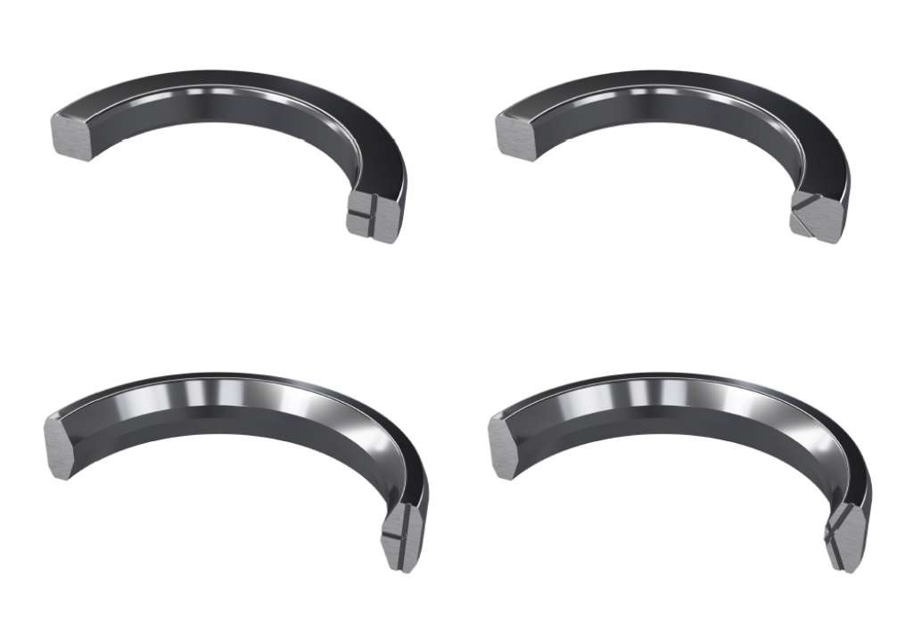
The Offshore Oil & Gas industry imposes strict requirements on these gaskets due to the critical conditions and corrosion risks typical of the subsea environment. To distinguish subsea Ring Type Joints from topside versions, the suffix “S” is added, indicating the presence of a through-hole in the gasket cross-section to equalize pressure, preventing pressure lock during subsea assembly.
SBX and SRX Style gaskets are specifically designed for use in all relevant equipment and in compliance with API 17D. API 17D defines two options for the pressure relief holes, referred to as Option A and Option B. Apart from this feature, API 17D-compliant SBX Ring Type Joints remain identical to API 6A-compliant BX Ring Type Joints.
Norsok IX Seal Ring gaskets are designed for use in compact flange connections, as specified in the Norsok L-005 standard.
When the flanged connection is assembled, bolt tightening presses the flange against the conical sealing surfaces located on the outer diameter of the IX Seal Ring. This type of joint is typical of compact flange systems, designed to operate under extreme pressure and temperature conditions, ensuring high sealing performance in reduced spaces.
The compact flange assembly incorporates two sealing barriers: a primary one, provided by the IX Seal Ring itself, and a secondary one, resulting from the mechanical stress applied to the flange heel during tightening. As with API Ring Type Joint gaskets, IX Seal Rings are manufactured with extremely tight tolerances and under strict quality controls to ensure precise matching with the sealing surfaces.
The choice of materials plays a crucial role in ensuring mechanical strength and chemical compatibility, especially in environments subject to chloride, H₂S, or CO₂ corrosion. To facilitate identification and prevent errors during installation, IX gaskets are marked with a color code indicating the metal type, in accordance with NORSOK L-005 standards.
IX Seal Rings represent a highly reliable solution for offshore plants, pipelines, and critical applications in the oil & gas industry.
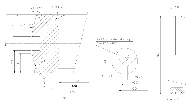
Another type of metallic gasket for flanged connections is the Lens Gasket, specifically designed for flanges where the sealing surface has a spherical geometry.
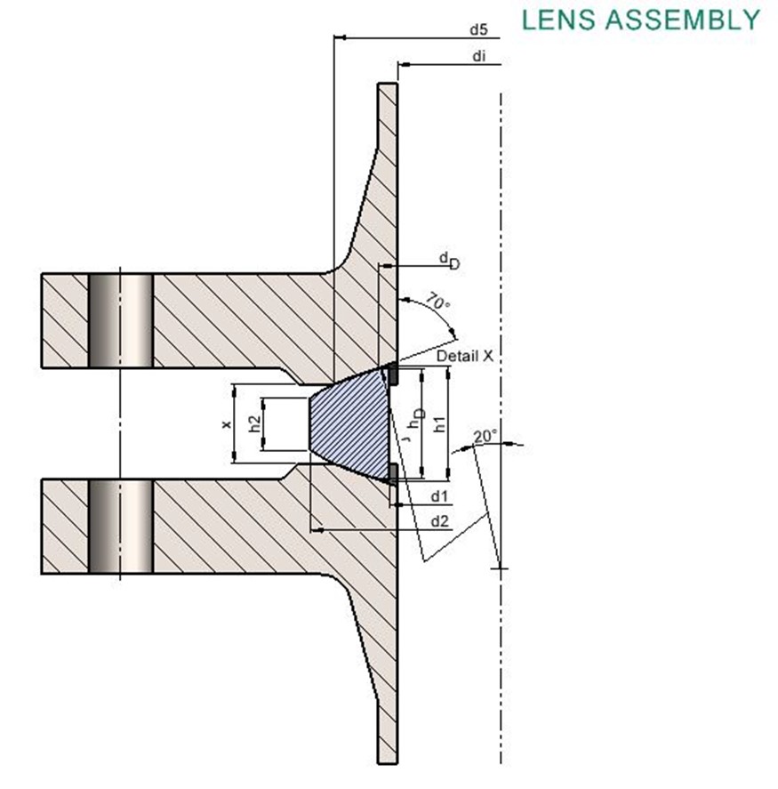
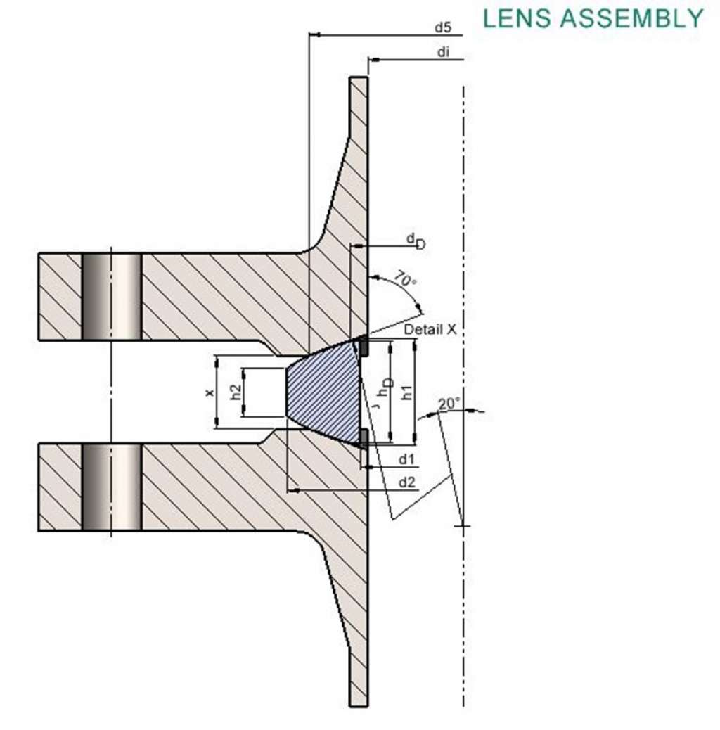
Unlike common flat gaskets, the Lens Gasket is characterized by a convex surface that mates with the concave counterpart of the flange, ensuring an extremely secure metal-to-metal seal. This configuration provides high sealing integrity even under intense thermal cycling and in operating conditions with very high pressures and temperatures. The operating principle is based on the controlled deformation of the gasket, whose spherical surface is uniformly compressed into the flange seat, generating a narrow and reliable contact area. The system is mainly defined by the DIN 2696 standard, although it can be adapted to other flange standards through geometric modifications. This standard specifies not only dimensions but also material requirements and typical operating conditions.
As with all metallic gaskets, it is essential that the material of the Lens Gasket is softer than that of the flange, so that plastic deformation is concentrated on the gasket and not on the flange surface, ensuring reusability and preventing permanent damage. This hardness difference, combined with proper bolt load distribution, allows effective sealing without overloading the contact surfaces. The materials permitted by DIN 2696 mainly include carbon steels and stainless steels, but special alloys can be used on request for applications involving aggressive chemicals or more demanding requirements. Lens Gaskets are used in highly critical fields, such as reactors, chemical plants, and high-pressure systems, where reliability, repeatability, and compatibility with extreme thermal cycles are essential requirements.