Carrara's product range grows again and this time includes the Monolithic Insulation Joints which are designed, manufactured and tested at its HQ in Adro - Brescia, Italy.
The Monolithic Insulation Joints Carrara are strictly assembled in accordance with the requirements of the main international rules and can be customized according the the Client’s specifications.
The purpose of insulating joints installation on gas and oil pipelines is to ensure electrical isolation among sections of pipelines and prevent detrimental electrochemical interaction among the sections themselves. Insulating joints are also used to ensure effective current spreading on cathodic protection systems.
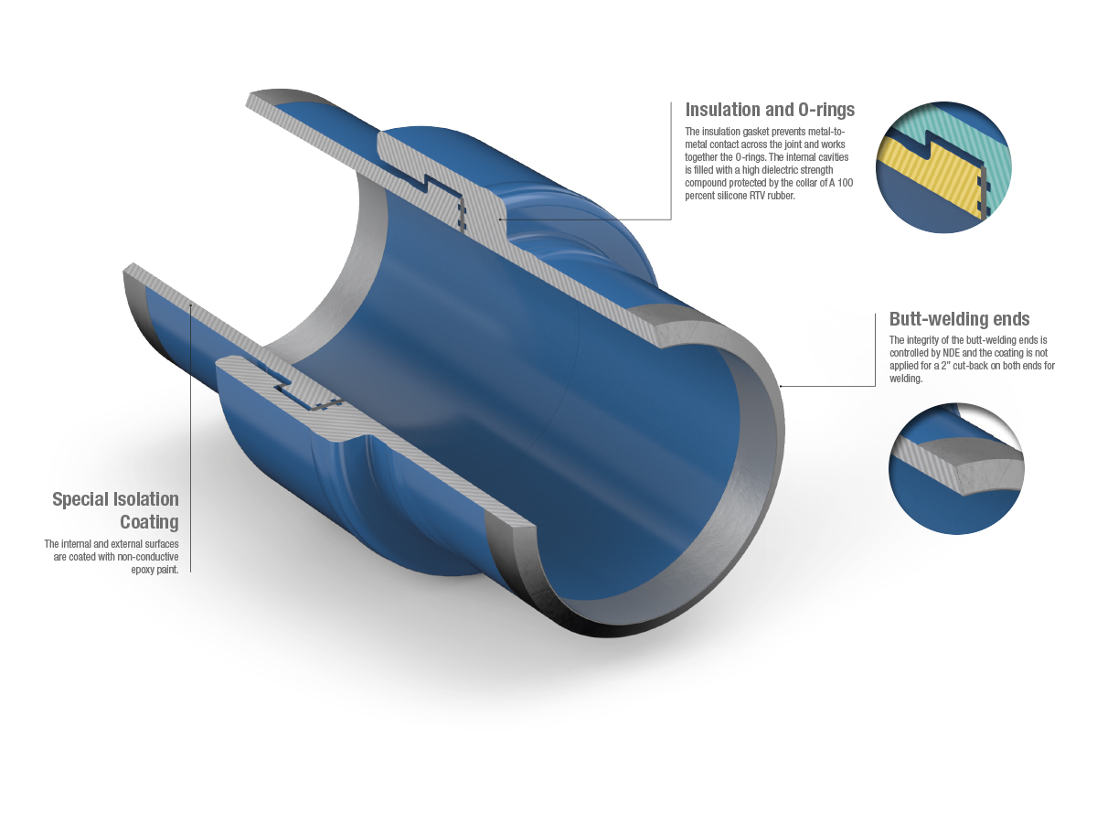
The insulating joint is suitable for installation either under, or above ground and it shall be installed on pipeline by means of girth welding it between two sections of pipeline itself. The high insulation resistance is assured by three different parts of the Monolithic Joint.
First of all the insulation gasket which prevents the metal-tometal contact across the internal flanges, second the internal cavities filled with an high dielectric strength compound which prevents the dielectric arc across the collar and the pipe pup.
Finally the internal and external surfaces are coated with a non-conductive epoxy paint. The Monolithic Isolation Joints are boltless and completely assembled in the factory in order to be ready for on site erection.
Monolithic isolation joint
The Monolithic Isolation Joint is composed of 5 metal parts, mutually welded, of two electrical insulation elements which are glass-reinforced epoxy resins and thermosetting epoxy resins (filler); finally of two sealing elements which are usually NBR or FKM O-Rings.
The final internal and external coating with epoxy paint with an high dielectric coefficient is the last step of the manufacuring.
The main technical and dimensional features required are deeply detailed by the Customer in the MR Material Requisition.
The pipe pup currently used are seamless tubes standard API 5L, but pipes that refer to other standards can also be used. The flanges (forged rings) ordinarily refer to ASTM A105 or ASTM A370 or ASTM A694. The welds are Butt Welds according to the ASME IX equirements.
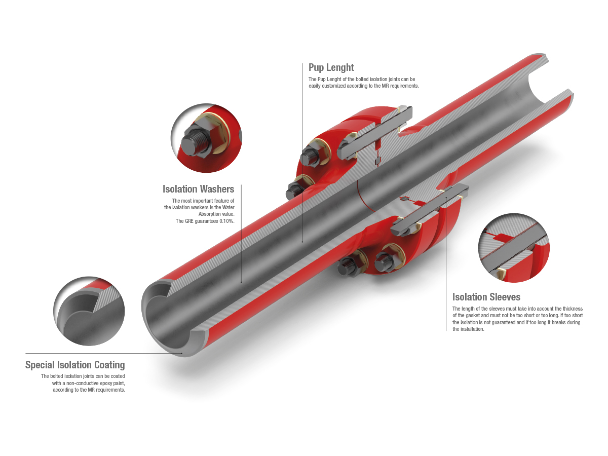
Bolted isolation joint
The bolted isolation joins, like the monolithic, are used for electrical sectioning and improving cathodic protection systems against corrosion of gas, water and petroleum pipelines. They can be arranged with all materials using RF or RTJ ASME B16.5 and API 6A flanges.
Special thermal treatments and coatings can be applied according to the Client’s requirements. The bolted isolation joints can be equipped with several isolating materials with great electrical, mechanical and aging resistance requirements. The materials with higher added value for making the insulation kits are GRE - Glass Reinforced Epoxy Resin. Composite Materials, while those using Phenolic Resin have less technological characteristics due to their high water absorption factor and low mechanical strength.
The gaskets can also be made with PTFE or compressed fibre (CSF), while the sleeves are usually mad with GRE, Mylar, Nomex or Polyethhylene.
Inside the monolithic isolation joint
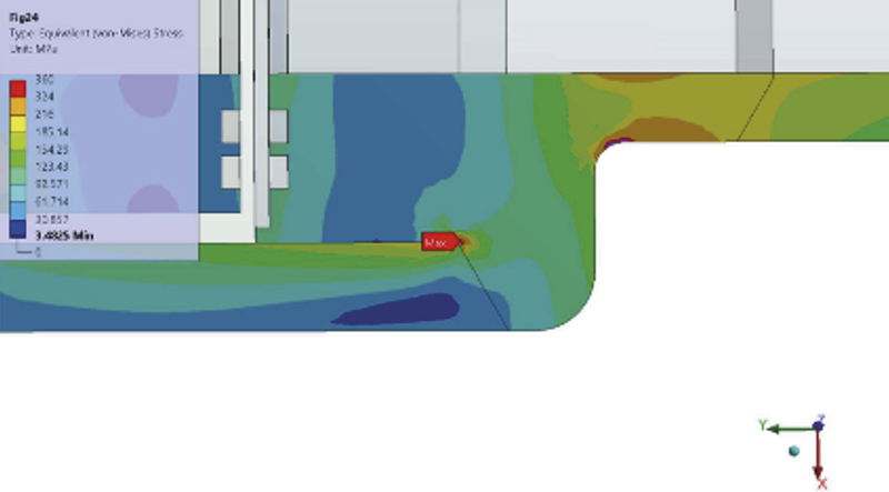
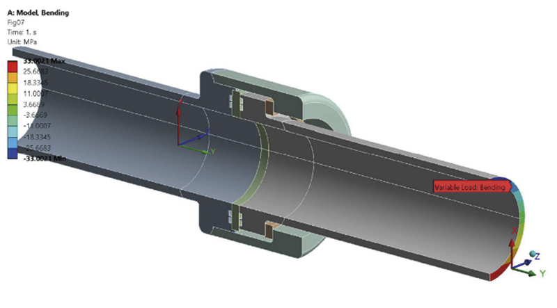
The verification of the resistance of the joints is carried out by a finite element analysis. The characteristics of the model and the results obtained are part of the technical report supplied to the Customer. A solid quadratic finite element model of the joint is created. It exploits the symmetry of the problem and includes half of the joint integrated by symmetry constraints on the section plane; the thickness of the pipe was reduced by 12% to take into account the manufacturing sub-tolerance.
For the design, the standards and methodologies adopted are those of ASME VIII Division 1 Appendix 2. For pipe-pups The main references are ANSI B31.4 and ANSI B31.8 where applicable. All welds are Butt Welded with bevel design as per API 5L and welding requirements as per ASME IX. The sealing weld is in accordance with ASME Section VIII Div. 1. The NDT checks used are the usual ones (RX, UT, MT, LP).
The mechanical requirements that influence the design must be defined. These are the Design Factor (0.5 ÷ 1.0) and the Design Load as a function of the SMYS value related to the thickness of the components and to the material. The isolation material currently used are GRE - Glass Epoxy Resin - combined with HNBR or FKM as sealing O - Ring material. The internal and external coating shall be a fusion-bonded epoxy resin selected in accordance with the Customer requirements.
Definitions
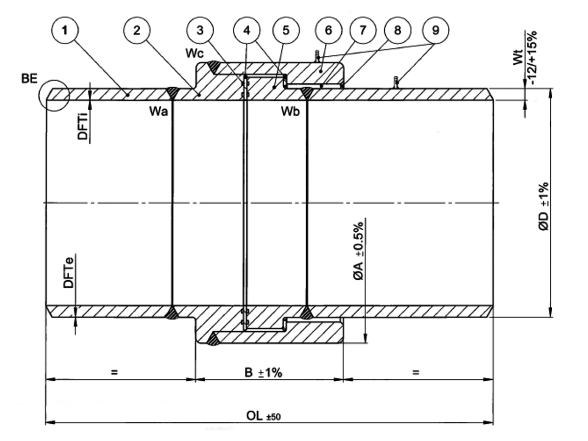
| 1 | Pipe Pups A and B |
| 2 | Flange A |
| 3 | O-rings |
| 4 | Insulation Rings |
| 5 | Flange B |
| 6 | Collar |
| 7 | Dielectric Epoxy Resin |
| 8 | RTV Sealant |
| 9 | Connector |
| ANSI | American National Standards Institute |
| API | American Petroleum Institute |
| ASME | American Society of Mechanical Engineers |
| ASTM | American Society for Testing Material |
| Cathodic Protection | A technique used to control the corrosion of a metal surface by making it the cathode of an electrochemical cell |
| Dielectric Material | Gaskets, fillers or insulating material that prevents the flow of electric current up to a predetermined voltage |
| Dielectric Strenght | The maximum electric field strength that a non conductive material can withstand without breaking |
| Forged Steel Fittings | Solid pieces of steel are forced into fitting shapes under very high temperature and pressure and then machined into final form |
| Galvanic Action | When two different metals are immersed in the same electrolytic solution and electrically connected, there is an exchange of atoms carrying an electrical charge between them. The anode metal with the upper electrode potential corrodes with the protected cathode |
| ID | Internal diameter of a pipe measured from the internal edges |
| Insulation Resistance | The resistance to electrical current leakage through the insulation material |
| Nominal Pipe Size | NPS |
| OD | Outer diameter of a pipe measured from the outer edges |
| PWHT | Post-welding heat treatment |
| SCH or Schedule | Pipe classification, number assigned to different pipe's wall thicknesses. |
| SMLS | Seamless tube, pipe or tube formed by drilling a steel billet. |
| SPEC | Specification |
| Specified Minimum Yield Strength (SMYS) | The minimum specified yield strength for the steel tube; it is an indication of the slightest stress causing permanent deformation |
| STD | Standard |
| Thermosetting | The process in which a prepolymer in a solid or viscous solid state irreversibly transforms into an infusible and insoluble polymers by hardening |
| WT | Wall thickness, equivalent to the wall thickness of the pipe |
MR - Material Requisition
Example of the minimum set of required information
| Customer | ACME OIL |
|---|---|
| Project | ACME OIL Plant 32-A |
| Item | Monolithic Isolation Joint, NPS-06 ASME Class 600 LBS |
| Manufacturer | Carrara Spa |
| Supplier | Carrara Spa |
| Model No. | MJ-005/A |
| General Data | |
| Size: | NPS-06 |
| ASME Class | # 600 |
| Type | Monolithic Isolation Joint |
| Service | Raw Gas |
| Sour Service | No |
| Adjacent main pipe W.T. (mm) | 12.7 mm |
| Adjacent main pipe material | API 5L Gr X65, Seamless, PSL 2 |
| Installation | Aboveground |
| Piggabilty | Yes (suitable for intelligent pigging) |
| Design | |
| Pipeline design code | ASME B31.8 |
| Design factor | 0.50 |
| Allowable stress value | 50% of SMYS |
| Design life | 20 years |
| Design temperature | -10 to 70°C |
| Design pressure | Class 600 LBS |
| Corrosion allowance | 6 mm |
| Outer coating DFTe | 300 µm |
| Outer Colour | RAL 1021 |
| Inner lining DFTi | 450 µm |
| Material Specifications | |
| Body | ASTM A 694 F65 |
| Pups (Material / Thickness) | API 5L Gr X65 seamless, PSL.2, 12.7 mm |
| Insulating material | Vendor to provide material's details |
| Sealing material | Vendor to provide material's details |